Specifications

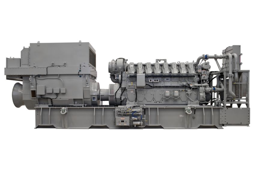
C280-8

Specifications

Minimum Rating2300 ekW3084 kV·A
Maximum Rating2710 ekW3634 kV·A
EmissionsIMO Tier II/EPA Marine Tier 2
AspirationTurbocharged-Aftercooled
Bore280 mm11 in
Displacement148 l9031 in³
Engine ControlElectronic ADEM™ A3
Fuel SystemEUI
Generator Set ControlGenerator Monitoring System (GMS)
Oil Change Interval1000 h1000 h
Stroke300 mm11.8 in
Weight49000 kg108027 lb
Height3406 mm134.1 in
Length8140 mm320.5 in
Width2326 mm91.6 in
Cooling System - Engine530 l140 gal (US)
Lube Oil System - Refill1094 l289 gal (US)

C280-8 Standard Equipment

  • Product Consist
    • The engine is a turbocharged, aftercooled, four-strokecycle-diesel, electronic unit injection engine with a280 mm (11 in) bore by 300 mm (11.8 in) stroke. SAEstandard rotation is counterclockwise as viewed from therear of engine flywheel.
  • Emissions Certifications
    • GL and CCS approved IMO certificate — includesstatement of compliance or Engine International AirPollution Prevention (EIAPP) certificate, supplied by theRecognized Organization (RO) where available, andtechnical file to be kept on board per IMO regulations.
  • Marine Certification Society type-approval
    • ABS, BV, CCS, DnV, GL, LRS
    • Spray shielding to meet SOLAS regulations for flammablefluids
  • European Certifications
    • Declaration of Incorporation for EU Machinery Safety
    • Directive and EU Low Voltage Safety Directive
  • Air Inlet System
    • Fresh water aftercooler, corrosion resistant coated (airside)
    • Air inlet shutoff
    • Turbocharger, rear-mounted, oil lubricated
  • Control System
    • Single Cat ADEM A3 electronic engine control module withelectronic unit injector fuel system, rigid wiring harness(10 amp 24V power required to drive electronic enginecontrol modules)
  • Cooling System
    • Gear-driven jacket water (JW) pump
    • Gear-driven separate-circuit aftercooler/oil cooler (AC/OC) pump
    • Engine coolant water drains
  • Exhaust System
    • Dry, gas tight exhaust manifold
  • Fuel System
    • Distillate fuel (requires viscosity ranging from 1.4 cStto 20 cSt at 38°C)
    • Fuel pump, gear-driven
    • Fuel transfer pump (mounted on left-hand side)
    • Duplex fuel filters, rear-engine-mounted
    • Electronically controlled unitinjectors
  • Lube system
    • Centrifugal oil filters with single shutoff, service-side enginemounted on cylinder block inspection covers (includesinstalled oil lines and single shutoff valve), filters centrifugebypass oil from the main lubricating oil pump (can be servicedwith the engine running)
    • Oil filler and dipstick
    • Oil pressure regulating valve
    • Dry engine-mounted sump system that gravity feeds intobase assembly integral sump
    • Engine-mounted duplex oil filter
    • Intermittent air prelube
    • Continuous electric prelube
    • Redundant prelube with continuous electric prelube andintermittent air prelube backup
    • Oil pan drain valves
    • Electric continuous prelube pump
    • Lube oil heater
    • Oil pump - gear drive
  • Protection System
    • Crankcase explosion relief valves
    • Alarm and shutdown during abnormal operation
  • Instrumentation
    • PLC-based system provides protection, monitoring, andcontrol housed in a NEMA 4 (IP66) enclosure.
  • General
    • Service Literature

C280-8 Optional Equipment

  • Air Inlet System
    • 90° adapter and straight adapters for air inlet to turbochargerAir cleaners
    • Air cleaners with Cat dry paper filter elements (approximately99.9% efficient at filtering SAE fine dust)
    • Soot filter
  • Control System
    • 4-20 mA load feedback signal
    • Load sharing module
    • Direct rack module
  • Cooling System
    • Separate Circuit Aftercooler (SCAC)
    • Customer water connections
    • Jacket water thermostats
    • AC/OC thermostats
    • Accessory module-mounted high volume expansion tank
    • Jacket water heater
    • Heat recovery connections and thermostats for use withwater maker system
    • ANSI connection adapters
  • Exhaust System
    • Exhaust manifold shields
    • Vertical or 30° outboard exhaust orientation options
    • Exhaust outlet expanders and weld flanges
  • Fuel System
    • Manual fuel priming pump
    • Duplex primary fuel strainer
    • Flexible fuel hose connections
  • Lube System
    • Dry engine-mounted sump system that gravity feeds intobase assembly integral sump
    • Engine-mounted duplex oil filter
    • Intermittent air prelube
    • Continuous electric prelube
    • Redundant prelube with continuous electric prelube andintermittent air prelube backup
    • Oil pan drain valves
    • Electric continuous prelube pump
    • Lube oil heater
  • Protection System
    • Wiring meets MCS requirements
    • Upgrade PLC monitor to industrial PC
    • Upgrades AC/OC, JW and start air pressure from contactorsto transducers
    • Raw water/sea water pressure transducer
    • Modbus communication
    • Beacon and horn
    • Single engine remote display monitor
    • Emergency pump start signal
    • Cabinet cooler
    • Generator power monitoring
    • Remote relay panel
    • Turbocharger speed sensors
    • Cylinder pressure relief valve
    • Oil mist detector
    • Flywheel and damper guards
  • Mounting System
    • Base aseembly
    • Vertically-restrained vibration isolators and weld plates
  • Starting System
    • Single turbine air starters
    • Boost control valve for extremely cold ambient conditions
    • Air start pressure reducing valves
  • General
    • Torsional couplings
    • Mounting groups for engine, generator, and base
    • Accessory module to mount attachments such as theexpansion tank, heat exchanger, instrument panel andengine controls, annunciator panel, alarm and shutdowncontactors, fuel strainer
    • Flywheel
    • Engine barring device options:
    • One-year storage preservation
    • Oceanic transportation shipping protection (shrink wrapand tarp)
    • Engine testing — certified dynamometer test, fuelconsumption test, rated speed performance test, overloadtest, minimum power setting, peak firing pressure test,turbo work cert and crankshaft work cert
    • Standard and project-specific witness testing
    • Spare parts kits
  • Literature
    • Project-specific installation drawings
    • Electrical schematics and P&ID drawings

Specifications

Minimum Rating2300 ekW3084 kV·A
Maximum Rating2710 ekW3634 kV·A
EmissionsIMO Tier II/EPA Marine Tier 2
AspirationTurbocharged-Aftercooled
Bore280 mm11 in
Displacement148 l9031 in³
Engine ControlElectronic ADEM™ A3
Fuel SystemEUI
Generator Set ControlGenerator Monitoring System (GMS)
Oil Change Interval1000 h1000 h
Stroke300 mm11.8 in
Weight49000 kg108027 lb
Height3406 mm134.1 in
Length8140 mm320.5 in
Width2326 mm91.6 in
Cooling System - Engine530 l140 gal (US)
Lube Oil System - Refill1094 l289 gal (US)

Equipment

C280-8 Standard Equipment

  • Product Consist
    • The engine is a turbocharged, aftercooled, four-strokecycle-diesel, electronic unit injection engine with a280 mm (11 in) bore by 300 mm (11.8 in) stroke. SAEstandard rotation is counterclockwise as viewed from therear of engine flywheel.
  • Emissions Certifications
    • GL and CCS approved IMO certificate — includesstatement of compliance or Engine International AirPollution Prevention (EIAPP) certificate, supplied by theRecognized Organization (RO) where available, andtechnical file to be kept on board per IMO regulations.
  • Marine Certification Society type-approval
    • ABS, BV, CCS, DnV, GL, LRS
    • Spray shielding to meet SOLAS regulations for flammablefluids
  • European Certifications
    • Declaration of Incorporation for EU Machinery Safety
    • Directive and EU Low Voltage Safety Directive
  • Air Inlet System
    • Fresh water aftercooler, corrosion resistant coated (airside)
    • Air inlet shutoff
    • Turbocharger, rear-mounted, oil lubricated
  • Control System
    • Single Cat ADEM A3 electronic engine control module withelectronic unit injector fuel system, rigid wiring harness(10 amp 24V power required to drive electronic enginecontrol modules)
  • Cooling System
    • Gear-driven jacket water (JW) pump
    • Gear-driven separate-circuit aftercooler/oil cooler (AC/OC) pump
    • Engine coolant water drains
  • Exhaust System
    • Dry, gas tight exhaust manifold
  • Fuel System
    • Distillate fuel (requires viscosity ranging from 1.4 cStto 20 cSt at 38°C)
    • Fuel pump, gear-driven
    • Fuel transfer pump (mounted on left-hand side)
    • Duplex fuel filters, rear-engine-mounted
    • Electronically controlled unitinjectors
  • Lube system
    • Centrifugal oil filters with single shutoff, service-side enginemounted on cylinder block inspection covers (includesinstalled oil lines and single shutoff valve), filters centrifugebypass oil from the main lubricating oil pump (can be servicedwith the engine running)
    • Oil filler and dipstick
    • Oil pressure regulating valve
    • Dry engine-mounted sump system that gravity feeds intobase assembly integral sump
    • Engine-mounted duplex oil filter
    • Intermittent air prelube
    • Continuous electric prelube
    • Redundant prelube with continuous electric prelube andintermittent air prelube backup
    • Oil pan drain valves
    • Electric continuous prelube pump
    • Lube oil heater
    • Oil pump - gear drive
  • Protection System
    • Crankcase explosion relief valves
    • Alarm and shutdown during abnormal operation
  • Instrumentation
    • PLC-based system provides protection, monitoring, andcontrol housed in a NEMA 4 (IP66) enclosure.
  • General
    • Service Literature

C280-8 Optional Equipment

  • Air Inlet System
    • 90° adapter and straight adapters for air inlet to turbochargerAir cleaners
    • Air cleaners with Cat dry paper filter elements (approximately99.9% efficient at filtering SAE fine dust)
    • Soot filter
  • Control System
    • 4-20 mA load feedback signal
    • Load sharing module
    • Direct rack module
  • Cooling System
    • Separate Circuit Aftercooler (SCAC)
    • Customer water connections
    • Jacket water thermostats
    • AC/OC thermostats
    • Accessory module-mounted high volume expansion tank
    • Jacket water heater
    • Heat recovery connections and thermostats for use withwater maker system
    • ANSI connection adapters
  • Exhaust System
    • Exhaust manifold shields
    • Vertical or 30° outboard exhaust orientation options
    • Exhaust outlet expanders and weld flanges
  • Fuel System
    • Manual fuel priming pump
    • Duplex primary fuel strainer
    • Flexible fuel hose connections
  • Lube System
    • Dry engine-mounted sump system that gravity feeds intobase assembly integral sump
    • Engine-mounted duplex oil filter
    • Intermittent air prelube
    • Continuous electric prelube
    • Redundant prelube with continuous electric prelube andintermittent air prelube backup
    • Oil pan drain valves
    • Electric continuous prelube pump
    • Lube oil heater
  • Protection System
    • Wiring meets MCS requirements
    • Upgrade PLC monitor to industrial PC
    • Upgrades AC/OC, JW and start air pressure from contactorsto transducers
    • Raw water/sea water pressure transducer
    • Modbus communication
    • Beacon and horn
    • Single engine remote display monitor
    • Emergency pump start signal
    • Cabinet cooler
    • Generator power monitoring
    • Remote relay panel
    • Turbocharger speed sensors
    • Cylinder pressure relief valve
    • Oil mist detector
    • Flywheel and damper guards
  • Mounting System
    • Base aseembly
    • Vertically-restrained vibration isolators and weld plates
  • Starting System
    • Single turbine air starters
    • Boost control valve for extremely cold ambient conditions
    • Air start pressure reducing valves
  • General
    • Torsional couplings
    • Mounting groups for engine, generator, and base
    • Accessory module to mount attachments such as theexpansion tank, heat exchanger, instrument panel andengine controls, annunciator panel, alarm and shutdowncontactors, fuel strainer
    • Flywheel
    • Engine barring device options:
    • One-year storage preservation
    • Oceanic transportation shipping protection (shrink wrapand tarp)
    • Engine testing — certified dynamometer test, fuelconsumption test, rated speed performance test, overloadtest, minimum power setting, peak firing pressure test,turbo work cert and crankshaft work cert
    • Standard and project-specific witness testing
    • Spare parts kits
  • Literature
    • Project-specific installation drawings
    • Electrical schematics and P&ID drawings

Related Products

Model.GetDictionaryValue(